
Research on borehole transient electromagnetic positioning method of azimuthal coil scanning detection
-
摘要:
利用掘进巷道超前探水钻孔进行钻孔瞬变电磁法探测钻孔孔壁外围远距离含水体,避免了常规测井方法仅能探测钻孔孔壁岩层的“一孔之见”。目前钻孔瞬变电磁法受全空间效应的影响,接收到的单分量响应不能判别异常体方位;多分量响应可以近似判断异常体的大致方位,但难以通过成像等直观有效的方法对其进行精确定位。基于钻孔瞬变电磁法和方位电磁波测井相关理论,提出了钻孔瞬变电磁法方位线圈扫描探测定位方法,采用方位线圈作为探测装置,减小线圈互感,增强钻孔瞬变电磁法的探测效果。同时,通过改变线圈旋转角,对钻孔孔壁进行360°扫描,形成钻孔径向全方位探测,旨在对钻孔孔壁外围岩体中的低阻体进行精确定位。首先推导方位线圈的互感解析表达式,探讨方位角对方位线圈互感的影响,通过数值计算确定最佳方位角取值。分别建立均匀介质和含低阻异常体的钻孔全空间三维地质−地球物理模型进行瞬变电磁场数值模拟,分析方位线圈的瞬变电磁法扫描探测多分量响应特征,总结方位线圈扫描探测瞬变电磁响应规律,确定了钻孔瞬变电磁法方位线圈扫描探测定位方法,即通过钻孔轴向和径向的瞬变电磁响应特征判别钻孔孔壁外围岩体中低阻异常体的位置。最后建立含2个低阻体的地质−地球物理模型,采用最佳方位角的方位线圈进行数值实验,验证了该方法能有效地判别低阻异常体的方位。研究表明:钻孔瞬变电磁法方位线圈扫描探测结果可以较好地反映钻孔径向外围岩体中低阻异常体引起的瞬变电磁场异常,全空间视电阻率成像结果分辨率较高。依据钻孔轴向和径向的瞬变电磁响应特征,钻孔瞬变电磁法方位线圈扫描探测定位方法对钻孔孔壁外围岩体中的低阻异常体具有较高的分辨率及定位精度。研究结果可以为钻孔瞬变电磁法方位线圈扫描探测定位方法的实际应用提供理论依据。
Abstract:The borehole transient electromagnetic method is used to detect the long-range water-bearing bodies around the borehole wall by using the advanced water exploration borehole in the heading roadway, which avoids the “one’s opinion in one hole” because the normal logging methods can only detect the rock layer of the borehole wall. At present, because of the whole space effect, the current borehole transient electromagnetic method cannot distinguish the orientation of abnormal bodies by the received single-component response, and it can approximate the orientation of abnormal bodies by multi-component response, but it is difficult to precisely locate and interpret the profiles by the visual and effective means such as imaging. Based on the theory of borehole transient electromagnetic method and azimuthal electromagnetic logging, this paper proposes a borehole transient electromagnetic positioning method with azimuthal coil scanning detection. The azimuth coil is used as the detection device to reduce the mutual inductance of the coil and enhance the detection effect of the borehole transient electromagnetic method. At the same time, by changing the rotation angle of the coil, the borehole wall is scanned by 360° to form a radial all-round detection of the borehole, aiming at a precise localization and profile interpretation of low-resistance abnormal bodies in the rock mass at the periphery of the borehole wall. Firstly, the authors derive an analytical expression for the mutual inductance of an azimuth coil, discuss the effect of azimuth angle on azimuth coil mutual inductance, and determine the optimum azimuth angle by numerical calculation. Secondly, a full-space 3D geological-geophysical model of the borehole with homogeneous medium and low-resistance abnormal bodies are established respectively and the numerical simulation of transient electromagnetic field is carried out. The multi-component response characteristics of the azimuthal coil scanning detection transient electromagnetic response are analyzed, and the law of transient electromagnetic response of azimuthal coil scanning detection is summarized, and the borehole transient electromagnetic positioning method with azimuthal coil scanning detection is determined. Namely, through the transient electromagnetic response characteristics of the axial and radial directions of the borehole, the position of the low-resistance abnormal bodies in the rock body at the periphery of the borehole wall is determined. Finally, by establishing the geological-geophysical model with two low-resistance bodies and using azimuth coils set to the best azimuth angle for numerical experiments, it is verified that the method can intuitively and effectively determine the orientation of low resistance abnormal bodies. The study shows that the azimuth coil scanning detection results of the borehole transient electromagnetic method can better reflect the transient electromagnetic field anomaly caused by the low-resistance abnormal bodies in the rock body at the periphery of the borehole wall, and the resolution of the full-space apparent resistivity imaging results is high. Based on the transient electromagnetic response characteristics of the axial and radial directions of the borehole, the borehole transient electromagnetic positioning method with azimuthal coil scanning detection has a high resolution and localization accuracy for the low-resistance abnormal bodies in the rock body at the periphery of the borehole wall. The research results provide a theoretical basis for the practical application of the borehole transient electromagnetic positioning method with azimuthal coil scanning detection.
-
我国煤矿水文地质条件复杂,矿井水害已经成为煤矿的主要灾害类型之一[1]。目前,根据含水地质体与围岩间的物性差异,可用地球物理方法进行含水体定位,用钻探进行验证。地球物理探测方法种类繁多,每种方法都各有优劣,如地震勘探对煤层赋存和地质构造的探测具有很好的效果,但对含水体的探测效果较差;矿井瞬变电磁法具有对含水地质体反应敏感、超前探测距离较大和探测方向指向性较好等优点,但仍存在受关断时间等因素影响存在探测盲区、易受巷道金属体干扰影响以及具有体积效应等不足,探查精度和分辨率不能满足当前煤矿水害防治要求[2-3]。钻探的优点是探查结果直观且准确,缺点是施工周期长、工作效率低和仅能探查钻孔所在位置地质情况等。如何利用钻孔将发射和接收装置或接收装置置于钻孔中进行孔中瞬变电磁法探测,可以克服常规矿井瞬变电磁法的不足,是当前的研究热点。
目前,在孔中观测瞬变电磁响应特征的工作方式可分为地−孔瞬变电磁法、隧(巷)−孔瞬变电磁法、钻孔瞬变电磁法和瞬变电磁测井。地−孔瞬变电磁法是发射线圈在地面、接收线圈置于钻孔中的探测方法,近几年来,利用地−孔瞬变电磁法进行钻孔外围含水体及导水通道探测在多座煤矿中得到应用,取得了较好的地质效果。王鹏等[4]采用正演方法分析了含水地质异常体的响应特征及异常体电导率、规模和相对钻孔距离变化等因素对异常场响应规律的影响,并采用最小二乘约束反演算法,通过反演拟合异常场实现异常体的空间定位。姚伟华等[5]采用时域有限差分法研究了地−孔瞬变电磁三分量的总场和异常场响应特征,利用物理试验验证了异常场三分量组合形态的不同可以判断异常体在钻孔的深度和方位。隧(巷)−孔瞬变电磁法是把地−孔瞬变电磁法的装置用于隧道或巷道中,其发射线圈在隧道或巷道,而接收线圈置于钻孔中,该方法在复杂地质条件下探查钻孔外围灾害地质体方面潜力较大。范涛[6]提出了巷道内动源发射,钻孔中三分量定向接收的方法,通过时域有限差分三维数值模拟证明了该方法对采空区探测具有实用性与有效性。孙怀凤等[7]提出了巷道内不动源发射,钻孔内动接收的探测方法,采用物理模拟的方法证明了该方法探测工作面前方含水构造的实用性和有效性。陈丁等[8]建立煤层底板存在含水低阻地质异常体模型,采用积分方程法进行数值模拟,分析了矿井全空间3D巷−孔瞬变电磁场响应特征。
钻孔瞬变电磁法(Borehole Transient Electromagnetic Method,BTEM)是将发射线圈和接收线圈同时置于钻孔内进行孔壁外围岩层的探测方法,该方法可以用于井下超前探水钻孔中,因探测装置距离钻孔外围目标体更近,可以接收到更强的地质异常体响应信号,同时远离巷道,有效地减弱了巷道内金属体等干扰,因而具有很好的发展潜力。
钻孔瞬变电磁法研究起步较晚,研究基础较为薄弱。WANG Bo等[9]提出了一种双发射六接收的钻孔瞬变电磁法,通过物理模拟证明了其在异常径向方位具有较好的分辨率,不同测点感应电压的差异可以定性地评价异常的径向深度。范涛[10]提出了一种在井下煤层压裂孔内探测的动源动接收的钻孔瞬变电磁三分量探测方法,采用物理模拟的方法确定了最理想的单孔瞬变电磁探测装置,实现了对煤层气压裂效果的检测和评价。笔者[11]提出了利用瞬变电磁法偶极装置进行钻孔径向扫描探测的方法,在钻孔径向断面图上可以高分辨显示异常体的形态和空间位置。辛成涛等[12]采用物理模拟的方法,利用屏蔽装置压制钻孔径向扫描探测中非探测方向的信号干扰,实现了对钻孔孔壁外围地质异常体的定位。与钻孔瞬变电磁法相近的方法是瞬变电磁测井。瞬变电磁测井中的方位电磁波测井在轴向线圈的基础上增加了径向和倾斜线圈,具有方位分辨能力,但探测范围仅限于井壁周围的小范围地层,孔中径向探测深度一般较浅[13]。
钻孔瞬变电磁法受钻孔空间限制,超小线圈装置的瞬变电磁场强度较弱,线圈互感较强,且常规钻孔瞬变电磁法无法准确地确定地质异常体的径向方位。采用屏蔽装置的钻孔瞬变电磁法可以确定地质异常体的径向方位,但缺点是增加了仪器的总体积,且不可避免地削弱了有效信号。因此,需要从减小互感和方位定位入手,探究一种简便高效的钻孔瞬变电磁法探测新方法。借鉴钻孔瞬变电磁法和方位电磁波测井相关理论和方法[14-16],笔者提出钻孔瞬变电磁法方位线圈扫描探测定位方法,即利用钻孔瞬变电磁法方位线圈对钻孔孔壁进行360°扫描,形成钻孔径向方向全方位探测,从而提高对地质异常体定位精度。
1. 全空间瞬变电磁场理论
1.1 全空间时域有限元正演方法
宏观电磁场的规律由麦克斯韦方程组描述,其微分形式为
$$ \left\{ \begin{gathered} \nabla \times {\boldsymbol{E}} = - \frac{{\partial {\boldsymbol{B}}}}{{\partial t}} \\ \nabla \times {\boldsymbol{H}} = {\boldsymbol{J}} + \frac{{\partial {\boldsymbol{D}}}}{{\partial t}} \\ \nabla \cdot {\boldsymbol{B}} = 0 \\ \nabla \cdot {\boldsymbol{D}} = q \\ \end{gathered} \right. $$ (1) 式中,E为电场强度,V/m;B为磁感应强度或磁通密度,T;t为时间,s;H为磁场强度,A/m;J为电流密度,A/m2;D为电通量密度或电位移,C/m2;q为自由电荷密度,C/m3。
对于各向同性介质,存在本构关系${\boldsymbol{D}} = \varepsilon {\boldsymbol{E}}$、${\boldsymbol{B}} = \mu {\boldsymbol{H}}$和${\boldsymbol{J}} = \sigma {\boldsymbol{E}}$。其中,$\varepsilon $为介电常数,F/m;$\mu $为磁导率,H/m;$\sigma $为电导率,S/m。令${\boldsymbol{H}} = \nabla \times {\boldsymbol{A}}$(其中,${\boldsymbol{A}} $为矢量磁位),利用矢量恒等式$ \nabla \times \nabla \times {\boldsymbol{A}}= - {\nabla ^2}{\boldsymbol{A}}+\nabla (\nabla \cdot {\boldsymbol{A}}) $和洛伦兹条件:$ \nabla \cdot {\boldsymbol{A}} + \sigma \phi + \varepsilon \dfrac{{\partial \phi }}{{\partial t}} =0 $,代入式(1)整理可得
$$ {\nabla ^2}{\boldsymbol{A}} = \mu \sigma \frac{{\partial {\boldsymbol{A}}}}{{\partial t}}+\mu \varepsilon \frac{{{\partial ^2}{\boldsymbol{A}}}}{{\partial {t^2}}} $$ (2) 假设断电后发射线圈电流瞬间降为0,由式(2)将涡流场的边值问题表示为
$$\left\{ \begin{array}{l} \nabla \times \left(\dfrac{1}{{{\mu _{\mathrm{r}}}}}\nabla \times {\boldsymbol{A}}\right) = {\mu _0}\left(\sigma {\boldsymbol{E}}+\varepsilon \dfrac{{\partial {\boldsymbol{E}}}}{{\partial t}}\right) \\ \nabla \cdot \left(\sigma {\boldsymbol{E}}+\varepsilon \dfrac{{\partial {\boldsymbol{E}}}}{{\partial t}}\right) = 0 \end{array} \right. $$ (3) 又${\boldsymbol{B}} = \nabla \times {\boldsymbol{A}}$,令${\boldsymbol{E}}+\partial {\boldsymbol{A}}/\partial t = - \nabla \phi $,由于${\varepsilon _0} \approx 8.854 \times {10^{ - 12}}$足够小,忽略二阶导数项并假定标量电位$\phi $为0可得
$$ \left\{ { \begin{gathered} \nabla \times \left(\frac{1}{{{\mu _{\mathrm{r}}}}}\nabla \times {\boldsymbol{A}}\right) = - {\mu _0}\left(\sigma \frac{{\partial {\boldsymbol{A}}}}{{\partial t}}\right) \\ \nabla \cdot \left( - \sigma \frac{{\partial {\boldsymbol{A}}}}{{\partial t}}\right) = 0 \\ \end{gathered} } \right. $$ (4) 其中,$\mu_{\mathrm{r}} $和$\mu_0 $分别为相对磁导率和真空磁导率。采用全局自适应网格细化方法,将整个求解域剖分成N个四面体单元,在任一四面体单元$e$中,矢量磁位A的插值函数可用该四面体单元各节点处的磁位近似表示为
$$ {A^e} \approx \sum\limits_{k = 1}^4 {N_k^e} {A_k} = \sum\limits_{k = 1}^4 ( N_k^e{A_{kx}}i + N_k^e{A_{ky}}j + N_k^e{A_{kz}}k) $$ (5) 其中,$i $、$j $、$k $为节点号;$N_k^e $为该单元在结点k形状函数。上述涡流场的边值问题利用伽辽金形式的加权余量法可转化为有限元离散化方程,经推导离散方程[17]可表示为
$$ \left(\frac{{\boldsymbol{M}}}{\Delta t}+\frac{2}{3}{\boldsymbol{K}}\right){\boldsymbol{u}}_{n+1}+\left(-\frac{{\boldsymbol{M}}}{\Delta t}+\frac{1}{3}{\boldsymbol{K}}\right){\boldsymbol{u}}_n=0 $$ (6) 其中,M为$\partial {\boldsymbol{A}}/\partial t$的系数矩阵;K为A的系数矩阵;${{\boldsymbol{u}}_n}$为时间节点$n$上的一个解向量。通过求解式(6)可得$(k + 1)\Delta t$时刻各个节点的矢量磁位向量A,由${\boldsymbol{B}} = \nabla \times {\boldsymbol{A}}$可计算磁感应强度$B$。
1.2 钻孔瞬变电磁方位线圈扫描探测装置形式
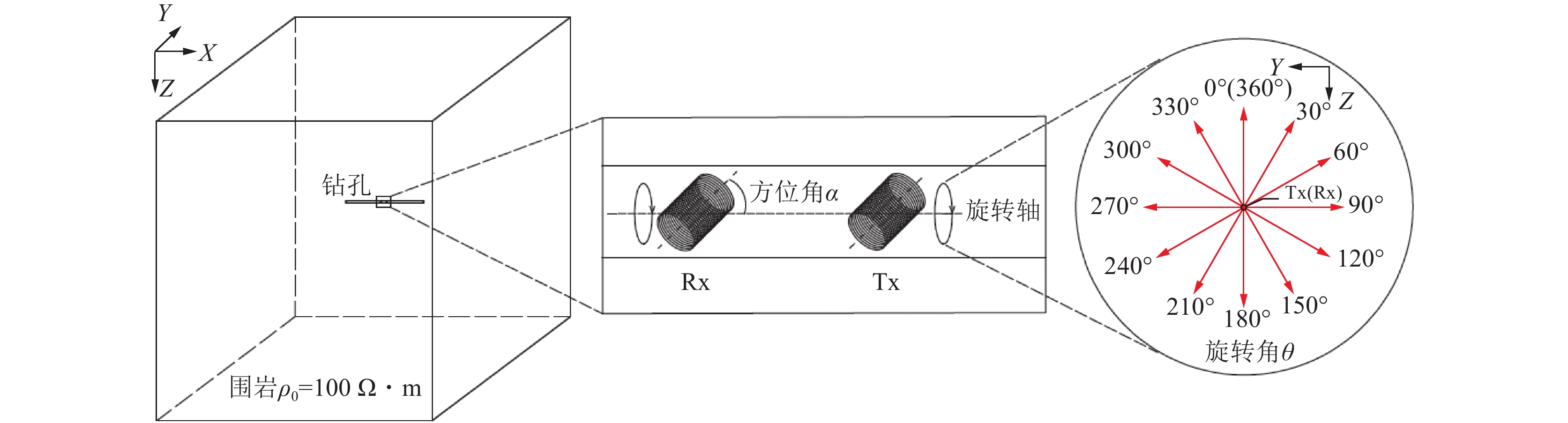
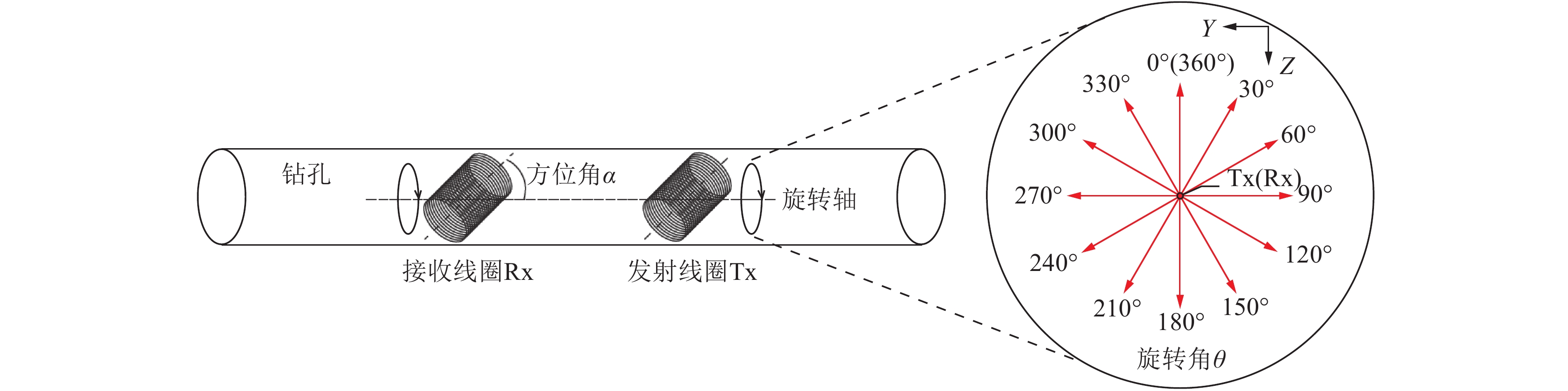
钻孔瞬变电磁法方位线圈扫描探测装置形式如图1所示,发射线圈和接收线圈横截面法线皆与钻孔轴线成固定的方位角$\alpha $,装置沿钻孔逐点移动,在同一测点将垂直钻孔轴线的截面分割成间隔30°的12个角度方向,方位线圈以中心点所在钻孔轴线为旋转轴旋转不同角度,接收线圈内产生的感应电动势作为观测数据。设定钻孔轴线方向为钻孔轴向,垂直钻孔轴线方向为钻孔径向。
![]() 图 1 钻孔瞬变电磁法方位线圈扫描探测装置示意Figure 1. Schematic diagram of BTEM azimuth coil scanning detection
图 1 钻孔瞬变电磁法方位线圈扫描探测装置示意Figure 1. Schematic diagram of BTEM azimuth coil scanning detection2. 方位角的选取
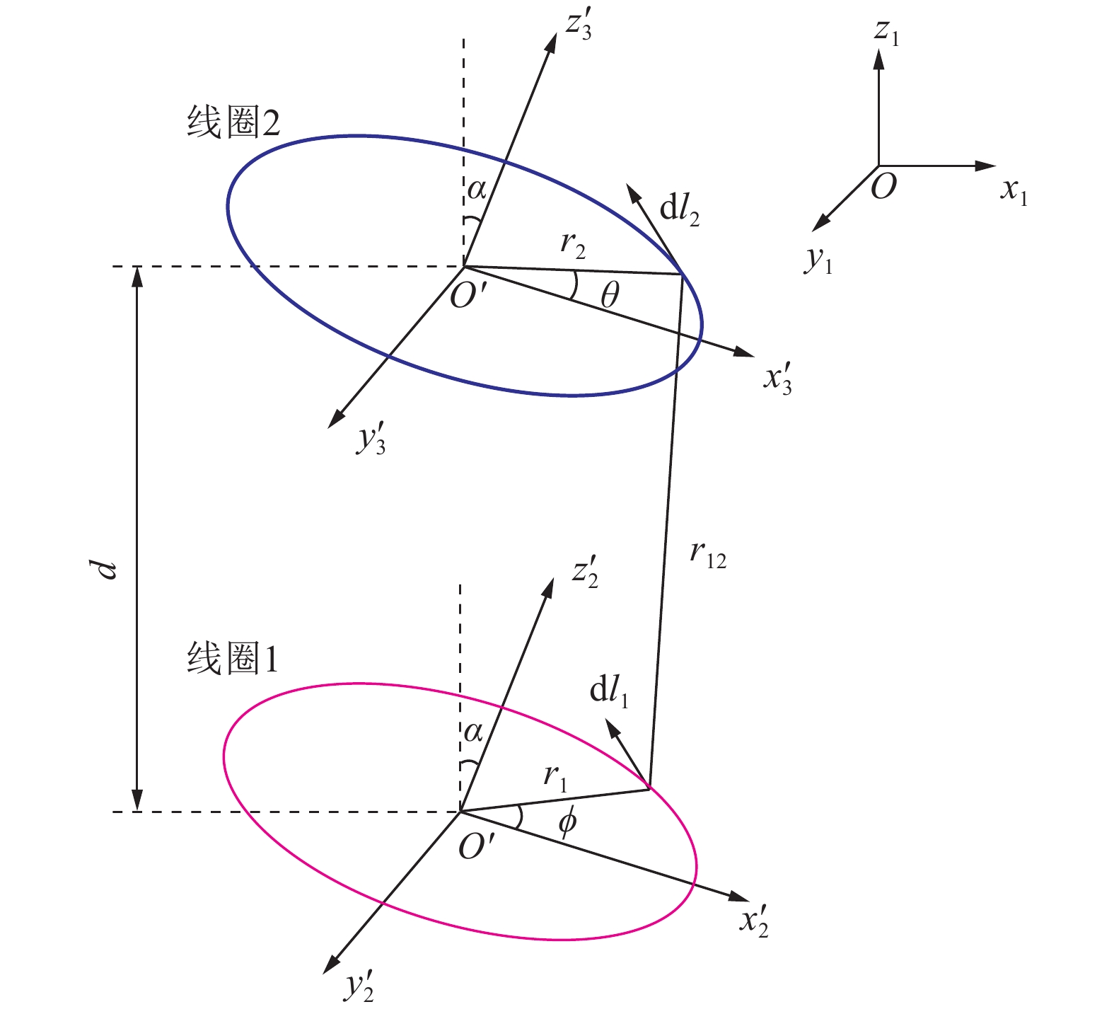
钻孔瞬变电磁法常采用的线圈的横截面半径不大于0.05 m的多匝线圈。多匝线圈电感会影响钻孔瞬变电磁探测效果,因此需要计算多匝圆形线圈的互感系数来确定方位角$\alpha $。图2为单匝圆形线圈互感计算示意,假设线圈1中心点位置不变,改变线圈2相对于线圈1在z轴上的空间位置,线圈1和线圈2线圈平面法线方向与钻孔轴线(z1轴)所成方位角$\alpha $相等,其中,d为收发距;${r_1}$和${r_2}$分别为线圈1与线圈2横截面的半径。
![]() 图 2 单匝圆形线圈互感计算示意Figure 2. Single-turn circular coil mutual inductance calculation diagram
图 2 单匝圆形线圈互感计算示意Figure 2. Single-turn circular coil mutual inductance calculation diagram相对于全局坐标系,微元${\mathrm{d}}{l_1}$和${\mathrm{d}}{l_2}$所在点在局部坐标系下的参数方程[18-19]为
$$ \left\{ {\begin{array}{l} {{x'_1}} = {r_1} \cos \phi \\ {{y'_1}} = {r_1} \sin \phi \\ {{{\textit{z}}'_1}} = 0 \end{array}}\right.$$ (7) $$ \left\{\begin{array}{l} {{x'_2}} = {r_2}\cos \theta \\ {{y'_2}} = {r_2}\sin \theta \\ {{{\textit{z}}'_2}} = 0 \end{array} \right. $$ (8) 经过坐标变换之后得到微元${\mathrm{d}}{l_1}$和${\mathrm{d}}{l_2}$所在点在全局坐标系下的参数方程为
$$ \begin{split} \left[ {\begin{array}{*{20}{l}} {{x_1}}\\ {{y_1}}\\ {{{\textit{z}}_1}} \end{array}} \right] = &\left[ {\begin{array}{*{20}{c}} {\cos \alpha }&0&{\sin \alpha }\\ 0&1&0\\ { - \sin \alpha }&0&{\cos \alpha } \end{array}} \right]\left[ {\begin{array}{*{20}{l}} {x_1^\prime }\\ {y_1^\prime }\\ {{\textit{z}}_1^\prime } \end{array}} \right]=\\&\left[ {\begin{array}{*{20}{c}} {{r_1}\cos \phi \cos \alpha }\\ {{r_1}\sin \phi }\\ { - {r_1}\cos \phi \sin \alpha } \end{array}} \right] \end{split} $$ (9) $$\begin{split} \left[ {\begin{array}{*{20}{l}} {{x_2}}\\ {{y_2}}\\ {{{\textit{z}}_2}} \end{array}} \right] =& \left[ {\begin{array}{*{20}{c}} {\cos \alpha }&0&{\sin \alpha }\\ 0&1&0\\ { - \sin \alpha }&0&{\cos \alpha } \end{array}} \right] \left[ {\begin{array}{*{20}{l}} {x_2^\prime }\\ {y_2^\prime }\\ {{\textit{z}}_2^\prime } \end{array}} \right] + \left[ {\begin{array}{*{20}{l}} 0\\ 0\\ d \end{array}} \right]=\\ & \left[ {\begin{array}{*{20}{c}} {{r_2}\cos \theta \cos \alpha }\\ {{r_2}\sin \phi }\\ { - {r_2}\cos \theta \sin \alpha + d} \end{array}} \right] \end{split}$$ (10) 微元${\mathrm{d}}{l_1}$和${\mathrm{d}}{l_2}$可以用几何方法求出,距离${r_{12}}$可以根据空间中两点距离公式计算得出
$$ {\mathrm{d}}{l_1} = {r_1}( - \sin \phi \cos \alpha x + \cos \phi y + \sin \phi \sin \alpha {\textit{z}}){\mathrm{d}}\phi $$ (11) $$ {\mathrm{d}}{l_2} = {r_2}( - \sin \theta \cos \alpha x + \cos \theta y + \sin \theta \sin \alpha {\textit{z}}){\mathrm{d}}\theta $$ (12) $$\begin{split} {r_{12}} =& \big[ {r_1^2} + {r_2^2} + {d^2} - 2{r_1}{r_2}(\cos \phi \cos \theta + \sin \phi \sin \theta ) - \\ &2d\sin \alpha ({r_2}\cos \theta - {r_1}\cos \phi ) \big]^{1/2} \end{split}$$ (13) 根据纽曼公式,得到不同空间位置下单匝圆形线圈之间的互感系数Ms的计算公式为
$$ \begin{split} {M_{\mathrm{s}}} =& \frac{\mu }{{4\pi }}\oint {\oint {\frac{{{\mathrm{d}}{l_1}{\mathrm{d}}{l_2}}}{{{r_{12}}}}} } = \\ & \frac{{\mu {r_1}{r_2}}}{{4\pi }}\oint {\oint {\frac{{\sin \phi \sin \theta + \cos \phi \sin \theta }}{{{r_{12}}}}} } {\mathrm{d}}\theta {\mathrm{d}}\phi \end{split} $$ (14) 多匝圆形线圈之间的互感系数ML计算公式为
$$ \begin{split} {M_{\mathrm{L}}}={n_1}{n_2}{M_{\mathrm{s}}} =& \frac{{{n_1}{n_2}\mu }}{{4\pi }}\oint {\oint {\frac{{{\mathrm{d}}{l_1}{\mathrm{d}}{l_2}}}{{{r_{12}}}}} } = \\ &\frac{{{n_1}{n_2}\mu {r_1}{r_2}}}{{4\pi }}\oint {\oint {\frac{{\sin \phi \sin \theta + \cos \phi \sin \theta }}{{{r_{12}}}}} } {\mathrm{d}}\theta {\mathrm{d}}\phi \end{split} $$ (15) 式中,${n_1}$和${n_2}$分别为线圈1和线圈2的匝数。
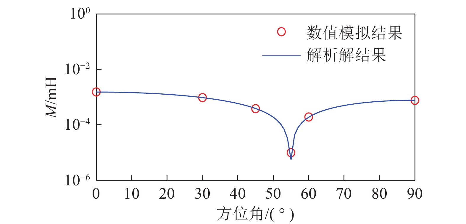
由式(15)可以看出,发射与接受线圈之间的互感与线圈匝数和半径成正相关,但不能看出发射与接受线圈之间的互感与方位角$\alpha $的关系,因此采用数值模拟与解析解计算的方法得到不同方位角$\alpha $对应的互感。
设介质磁导率$\mu $为真空磁导率${\mu _0}$,发射和接收线圈匝数100匝,横截面半径0.05 m,线圈的方位角由0°变化至90°,数值模拟与解析解计算结果如图3所示。从图3可以看出,随着发射和接收线圈方位角逐渐增大,发射和接收线圈之间的互感先减小后增大;方位角为55°时,发射和接收线圈之间的互感达到极小值,此时接收线圈接收到的磁通量最小。在方位电磁波测井中,线圈倾角(方位角)通常选择45°,既满足接收信号灵敏性,又满足接收信号强度[20]。钻孔瞬变电磁法方位线圈扫描探测需要解决远距离探测的技术难题,必须选取多匝线圈增加磁矩,从而造成发射与接收线圈之间互感较大。综合考虑,钻孔瞬变电磁法线圈方位角设置为55°,可以满足接收信号要求强度,同时可以极大程度上减小线圈互感,提高探测效果。因此,后续计算中线圈的方位角设置为55°。
![]() 图 3 不同线圈方位角对应的线圈互感Figure 3. Coil mutual inductance corresponding to different coil azimuth angles
图 3 不同线圈方位角对应的线圈互感Figure 3. Coil mutual inductance corresponding to different coil azimuth angles3. 方位线圈钻孔瞬变电磁场响应特征
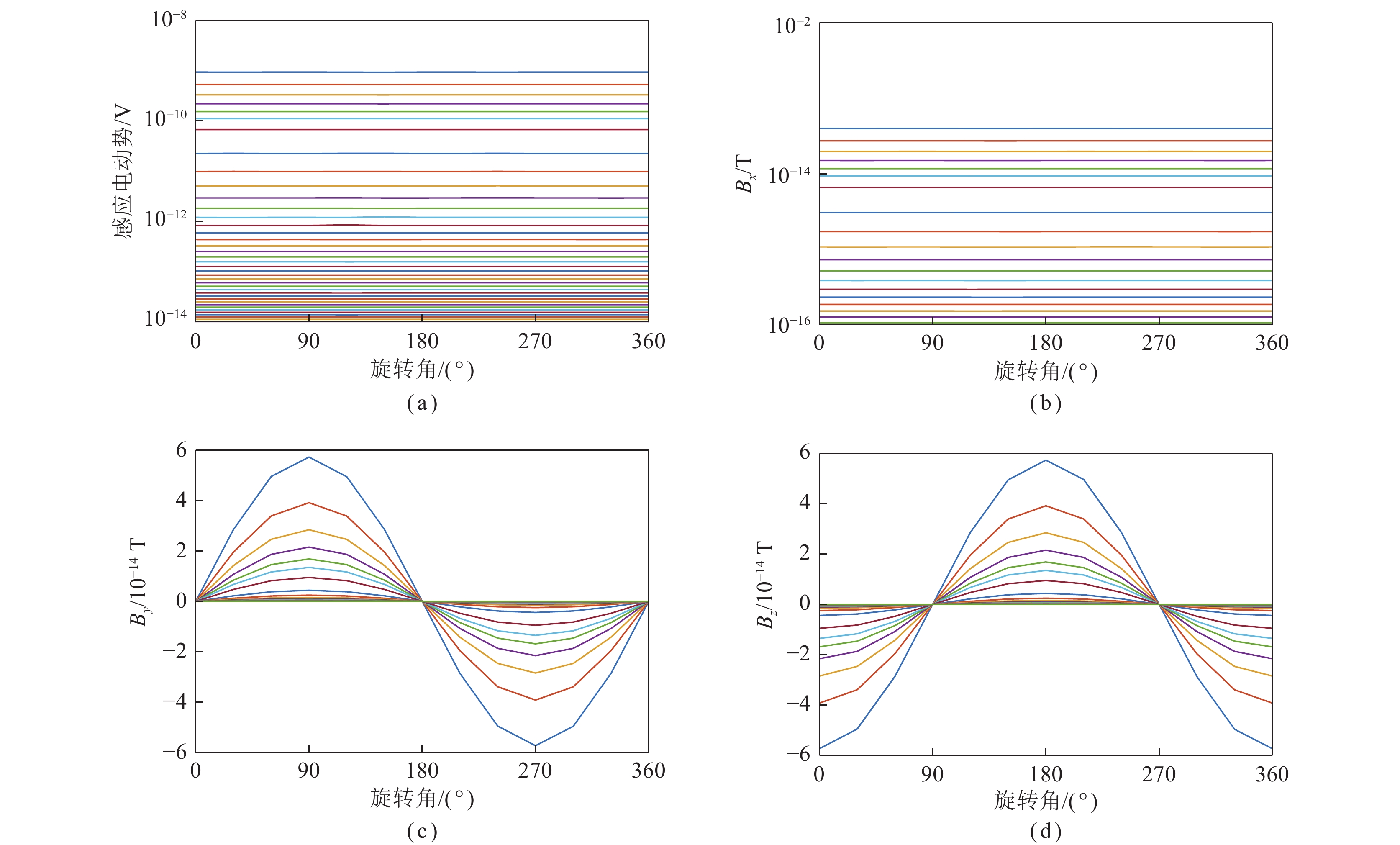
正确认识瞬态电磁场的响应特征是进行数据处理、解释和应用的基础,通过多分量的多测道曲线图可以直观的看出瞬变电磁场的响应规律。建立如图4所示钻孔全空间三维地质−地球物理模型,采用有限单元法进行全空间瞬变电磁场响应三维数值模拟。设全空间模型尺寸为500 m×500 m×500 m,围岩电阻率为100 Ω·m。发射线圈(Tx)与接收线圈(Rx)采用半径0.05 m、匝数100匝的多匝圆形线圈,收发距为1 m,线圈平面法线与钻孔轴向所夹方位角为55°,扫描旋转间隔为30°。钻孔泥浆电导率的变化对瞬变电磁响应影响极小,因此建立模型时忽略钻孔泥浆的影响[21]。
![]() 图 4 均匀介质钻孔瞬变电磁法三维地质−地球物理模型Figure 4. 3D geological-geophysical model in homogeneous medium of borehole TEM
图 4 均匀介质钻孔瞬变电磁法三维地质−地球物理模型Figure 4. 3D geological-geophysical model in homogeneous medium of borehole TEM图5为感应电动势$V$,磁场x分量${B_x}$,磁场y分量${B_y}$和磁场z分量${B_{\textit{z}}}$随旋转角$\theta $变化的多测道曲线,其中图5(a)、(b)所示的$V$和${B_x}$的多测道曲线均无异常响应,前者的多测道曲线无异常响应是因为其受全空间影响不随旋转角$\theta $变化而变化,后者的多测道曲线无异常响应是因为旋转角$\theta $以x轴为原点,仅在YZ平面内变化;图5(c)所示的${B_y}$的多测道曲线响应幅值可以看作是以旋转角$\theta $为变量的正弦函数,即${B_y} = A\sin \theta $,因此其会随旋转角$\theta $增加呈增大—减小—增大—减小的趋势,在90°取得极大值,在270°取得极小值。图5(d)所示的${B_{\textit{z}}}$的多测道曲线响应幅值可以看作是以旋转角$\theta $为变量的余弦函数,即${B_{\textit{z}}} = A\cos \theta $,因此其会随旋转角$\theta $增加呈减小—增大—减小—增大的趋势,在180°取得极大值,在0°和360°取得极小值。此种瞬变电磁响应规律可以作为钻孔瞬变电磁方位线圈扫描探测定位异常体的理论依据。
4. 钻孔瞬变电磁法方位线圈扫描探测定位方法
钻孔瞬变电磁法方位线圈扫描探测需要旋转发射和接收线圈进行探测,而对于同一地电模型,改变其旋转角$\theta $得到的瞬变电磁响应不同,这种瞬变电磁响应差异性可以作为全空间情况下定位低阻异常体的理论基础。图6为含低阻异常体的钻孔瞬变电磁法三维地质−地球物理模型,设围岩电阻率为100 $\Omega \cdot {\text{m}}$,低阻异常体电阻率为1 $\Omega \cdot {\text{m}}$,大小为10 m×10 m×10 m,发射电流为2 A,发射和接收线圈半径为0.05 m,匝数为100匝,收发距为1 m,方位角为55°,扫描旋转间隔为30°。以孔口为原点,低阻异常体中心(50,0,15)作为多点探测的测线中点,测点从(30,0,0)到(70,0,0)以5 m间隔进行布设,测点距5 m,共9个测点。
![]() 图 6 含低阻异常体钻孔瞬变电磁法三维地质−地球物理模型Figure 6. 3D geological-geophysical model with low resistance abnormal bodies of borehole TEM
图 6 含低阻异常体钻孔瞬变电磁法三维地质−地球物理模型Figure 6. 3D geological-geophysical model with low resistance abnormal bodies of borehole TEM4.1 钻孔轴向测线上异常体定位
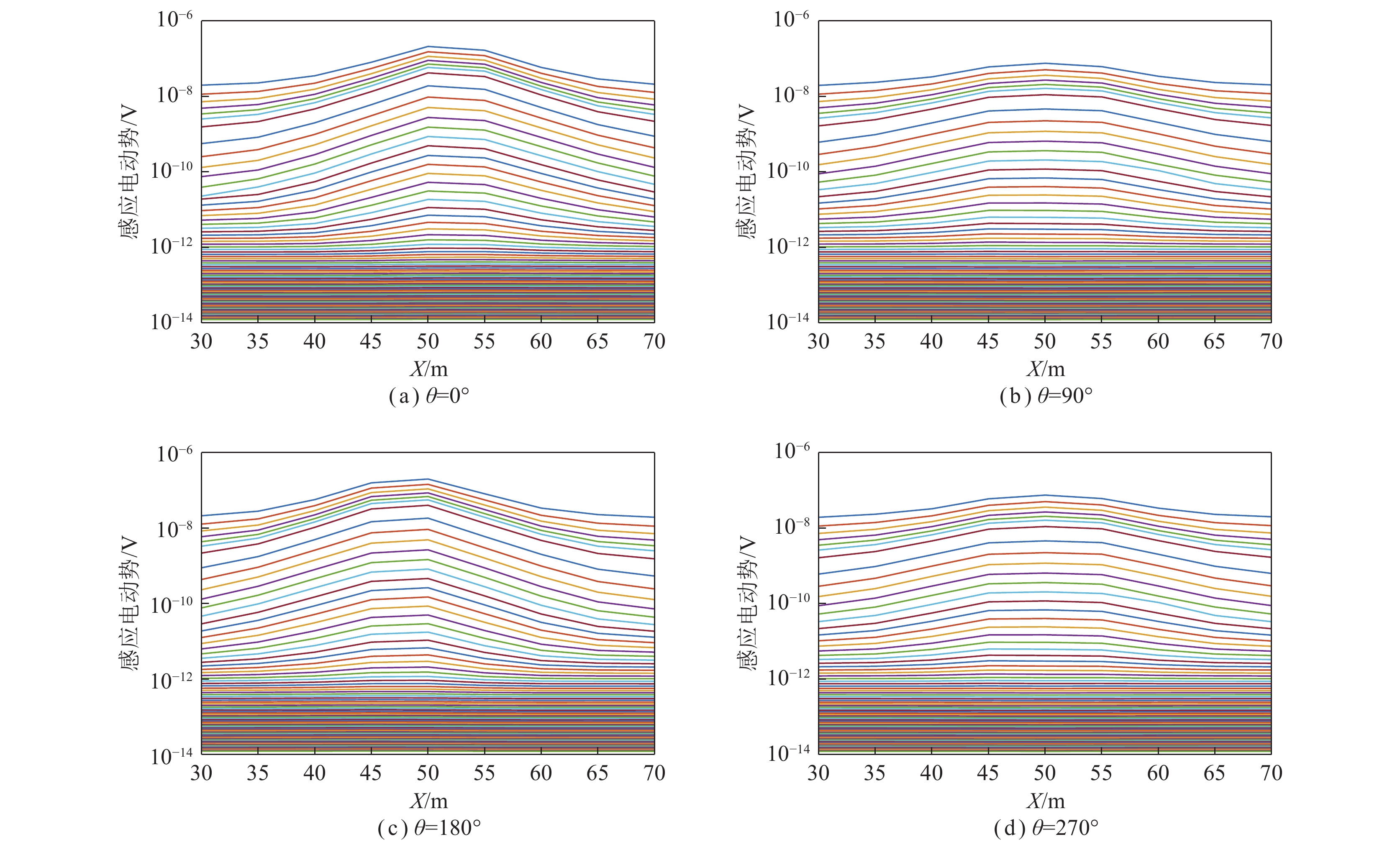
图7为钻孔轴向测线上多测点不同探测方向(不同旋转角)对应的感应电动势曲线,其中,横坐标为测点号,纵坐标为感应电动势。从图7可以看出,X=50 m测点的中、晚期感应电动势明显升高,该测点与钻孔径向下方低阻异常体中心位置相对应,说明低阻异常体引起瞬变电磁场衰减变慢,感应电动势增强,异常特征较明显,因此在钻孔轴向上可以判别低阻异常体位于X=50 m测点。通过对比可以看出,线圈轴线正对低阻异常体的方向异常响应最明显,感应电动势最强。
4.2 钻孔径向断面上异常体定位
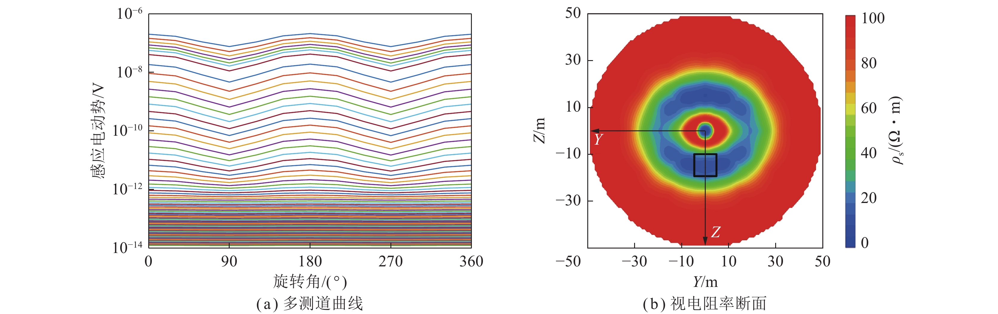
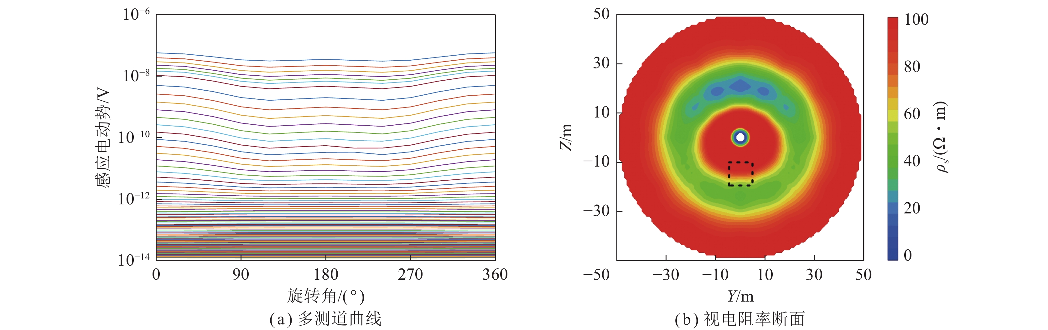
为了直观有效地判别低阻异常体所在径向方位,分别进行视电阻率计算和成像[22],分别选取钻孔中40、50和60 m三个测点的径向扫描探测结果进行分析。图8为钻孔中40 m测点径向扫描探测结果(X=40 m)。从图8(a)可以看出,$\theta = 180^\circ $的中、晚期感应电动势异常响应最强,与模型设置的低阻异常体所在径向方位相同;$\theta = 0^\circ \left( {360^\circ } \right)$的中、晚期感应电动势异常响应次之。从图8(b)可以看出,Z=−25~15 m,Y=−17~17 m位置处存在1处明显的低阻异常区域,与黑色虚线所代表的实际低阻异常相比较,可以看出异常区位置与模型中低阻异常体的位置存在约5 m的误差,异常区范围大于模型设置的范围,且相较于横向分辨率,异常区的纵向分辨率较高。
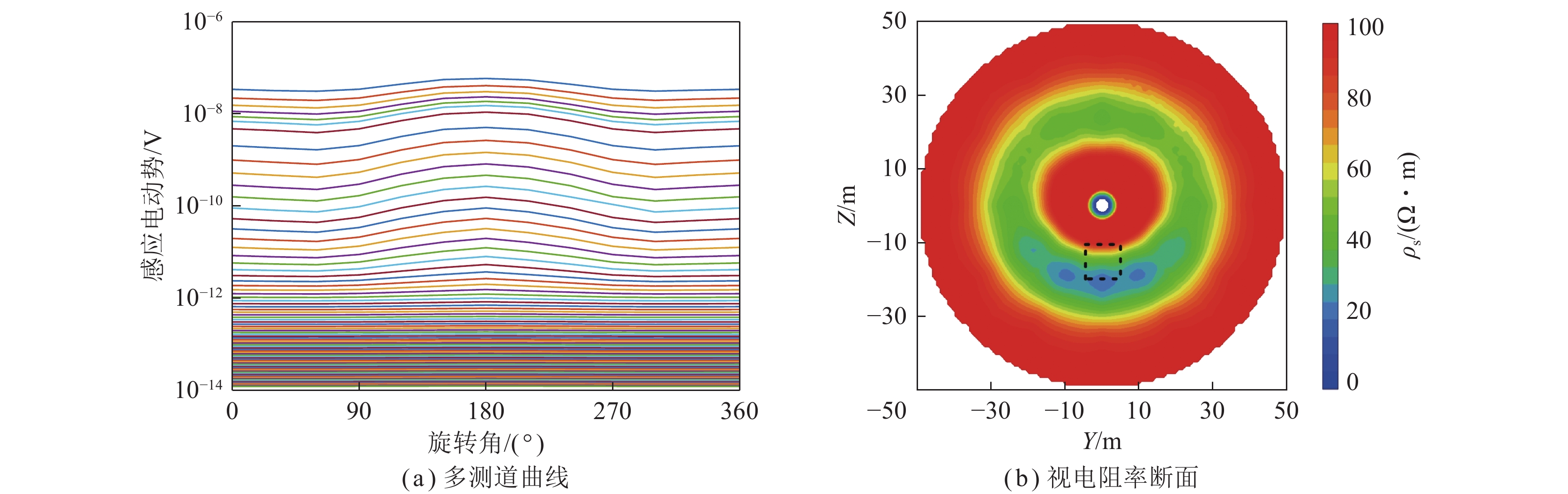
图9为钻孔中50 m测点径向扫描探测结果(X=50 m)。从图9(a)可以看出,$\theta = 180^\circ $和$\theta = 0^\circ (360^\circ )$的中、晚期感应电动势异常响应同时达到最强,不能指示低阻异常体所在径向方位。从图9(b)可以看出,Z=−20~−10 m,Y=−13~13 m位置处存在一处明显的低阻异常区域,与黑色实线所代表的实际低阻异常相比较,可以看出异常区位置与模型中低阻异常体的位置完全吻合,异常区范围大于模型设置的范围,且相较于横向分辨率,异常区的纵向分辨率较高。同时在上述低阻异常区关于Z=0对称的位置存在一处完全相同的镜像异常。
图10为钻孔中60 m测点径向扫描探测结果(X=60 m)。从图10(a)可以看出,$\theta = 0^\circ (360^\circ )$的中、晚期感应电动势异常响应最强,与模型设置的低阻异常体所在径向方位相差180°;$\theta = 180^\circ $的中、晚期感应电动势异常响应次之。从图10(b)可以看出,Z=15~25 m,Y=−17~17 m位置处存在一处明显的镜像低阻异常区域,与黑色虚线所代表的实际低阻异常相比较,可以看出异常区径向方位与模型中低阻异常体的径向方位相差180°,且相较于横向分辨率,异常区在纵向分辨率较高。
由上述分析可知,模型设置的低阻异常体径向方位与X=40 m测点瞬变电磁响应最强时对应的旋转角方向(180°)相同,与X=60 m测点瞬变电磁响应最强时对应的旋转角方向(0°)相反,因此可以将X=40 m测点瞬变电磁响应最强时对应的旋转角方向(180°)确定为低阻异常体的径向方位。
综上所述,钻孔瞬变电磁法方位线圈扫描探测时,低阻异常体的轴向方位为轴向上整体瞬变电磁响应最强的测点。低阻异常体的径向方位为轴向上整体瞬变电磁响应最强测点的相邻测点(轴向反方向)瞬变电磁响应最强时对应的旋转角方向,也为轴向上整体瞬变电磁响应最强测点的相邻测点(轴向正方向)瞬变电磁响应次强时对应的旋转角方向,相邻测点瞬变电磁响应最强时与次强时对应的旋转角相差180°。
5. 复杂地质模型数值实验
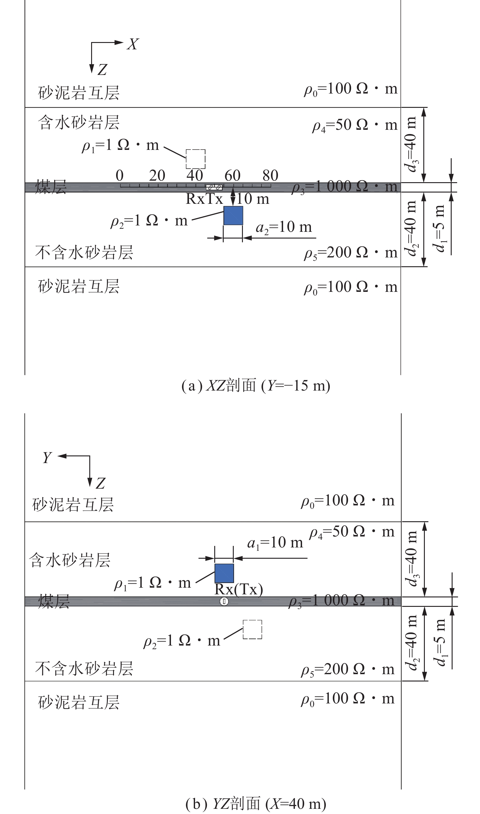
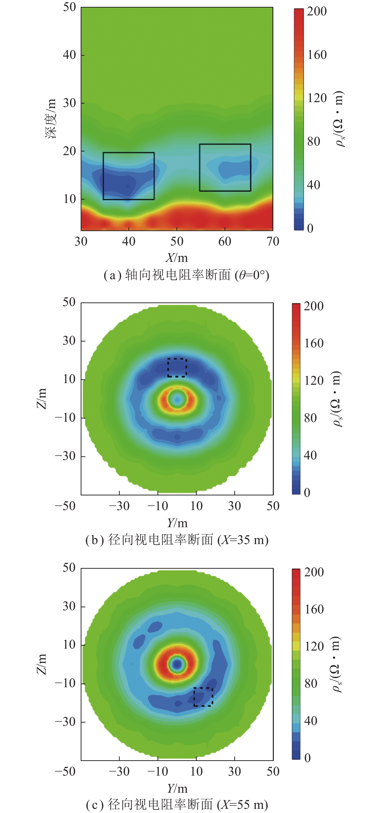
为检验钻孔瞬变电磁法方位线圈扫描探测定位方法在复杂介质中的应用效果,建立含煤层和2个低阻异常体的均匀全空间复杂地电模型,如图11所示,其中,图11(a)为低阻异常体2中心所在的XZ剖面,图11(b)为低阻异常体1中心所在的YZ剖面。设砂泥岩互层电阻率为100 $\Omega \cdot {\text{m}}$,含水砂岩电阻率为50 $\Omega \cdot {\text{m}}$,不含水砂岩电阻率为200 $\Omega \cdot {\text{m}}$,煤层电阻率为1 000 $\Omega \cdot {\text{m}}$,以孔口为原点,2个低阻异常体中心坐标分别为(40,0,−15)和(60,−15,15),电阻率均为1 $\Omega \cdot {\text{m}}$,发射电流为2 A,发射和接收线圈半径为0.05 m,匝数为100匝,收发距为1 m,方位角为55°,以(50,0,0)作为多点探测的测线中点,测点从(30,0,0)到(70,0,0)以5 m间隔进行布设,测点距5 m,共9个测点。
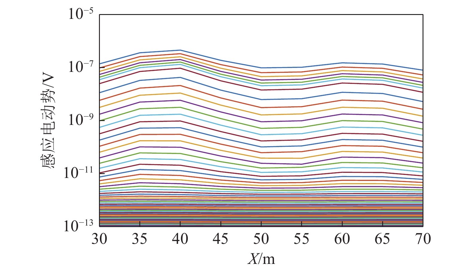
图12为轴向多测点探测结果($\theta = 0^\circ $),从图12可以看出X=40 m测点和X=60 m测点的中、晚期感应电动势明显升高,感应电动势峰值对应模型中低阻异常体的中心,说明低阻异常体引起瞬变电磁场衰减变慢,感应电动势增强,异常特征较明显。因此在钻孔轴向上可以判断存在2个低阻异常体,分别位于X=40 m和X=60 m测点。
![]() 图 12 轴向多测点探测结果($\theta = 0^\circ $)Figure 12. Axial multi-point detection results($\theta = 0^\circ $)
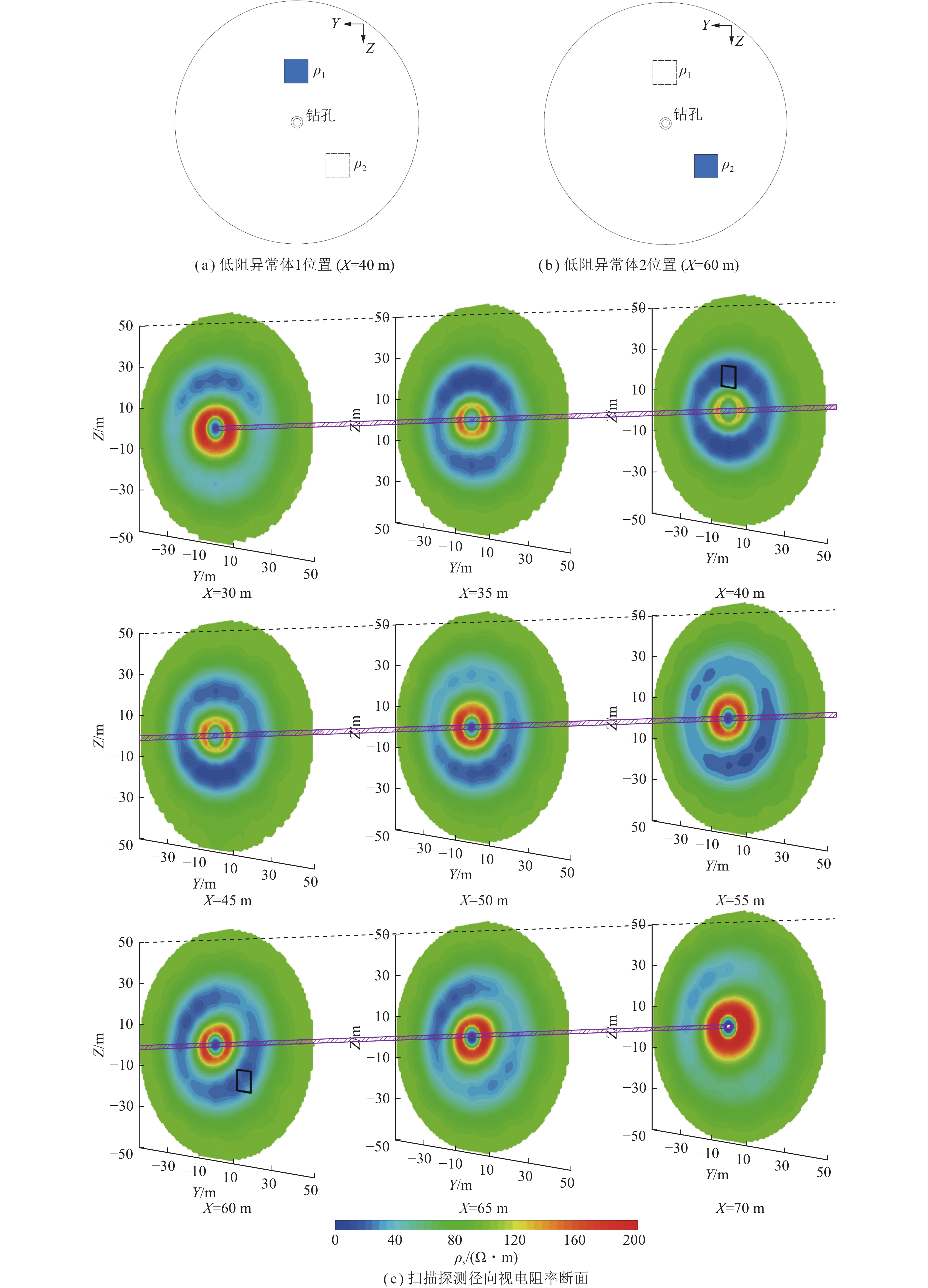
图 12 轴向多测点探测结果($\theta = 0^\circ $)Figure 12. Axial multi-point detection results($\theta = 0^\circ $)图13为扫描探测径向视电阻率断面与异常体位置,从图13(c)可以看出X=40 m测点和X=60 m测点出现了镜像异常,低阻异常区域的视电阻率与实际设置的异常体电阻率相比略大,低阻异常区域的视深度与实际设置的异常体的深度相比完全吻合;X=30~45 m测点的异常响应由低阻异常体1引起,其中X=30~35 m测点的低阻异常区域径向方位为0°,X=45 m测点的低阻异常区域径向方位为180°;X=50 m测点的异常响应由低阻异常体1和低阻异常体2同时引起,其低阻异常区域的径向方位为160°;X=55~70 m测点的异常响应由低阻异常体2引起,其中X=55 m测点的低阻异常区域径向方位为135°,X=65~70 m测点的低阻异常区域径向方位为315°。
![]() 图 13 扫描探测径向视电阻率断面图与异常体位置Figure 13. Diagram of scanning detection apparent resistivity radial section and abnormal bodies position
图 13 扫描探测径向视电阻率断面图与异常体位置Figure 13. Diagram of scanning detection apparent resistivity radial section and abnormal bodies position如图14所示,依据钻孔轴向和径向的瞬变电磁响应特征,选取X=40 m的相邻测点X=35 m测点的径向视电阻率断面反映低阻异常体1的径向方位如图14(b)所示,判别低阻异常体1的轴向方位为X=40 m,径向方位为0°;同样选取X=60 m的相邻测点X=55 m测点的径向视电阻率断面反映低阻异常体2的径向方位如图14(c)所示,判别低阻异常体2的轴向方位为X=60 m,径向方位为135°。数值模拟结果表明钻孔瞬变电磁法方位线圈扫描探测可以有效识别钻孔周围的低阻异常体,并且可以较准确地定位异常体的空间位置。
6. 结 论
(1)方位线圈系中发射与接收线圈的方位角均为55°时,2者之间的互感最小。
(2)对于均匀介质,钻孔瞬变电磁法方位线圈扫描探测接收到的$V$和${B_x}$的多测道曲线无异常响应;${B_y}$和${B_{\textit{z}}}$的多测道曲线响应幅值可以看作是以旋转角$\theta $为变量的正弦函数和余弦函数,即${B_y} = A\sin \theta $和${B_{\textit{z}}} = A\cos \theta $。
(3)钻孔瞬变电磁法方位线圈扫描探测的感应电动势多测道曲线可以清楚地显示低阻异常体引起的电磁场衰减异常响应。低阻异常体的轴向方位为轴向上整体瞬变电磁响应最强的测点,在轴向视电阻率断面上,低阻异常体位置表现为明显的低阻异常区。低阻异常体的径向方位为轴向上整体瞬变电磁响应最强测点的相邻测点(轴向反方向)瞬变电磁响应最强时对应的旋转角方向,在径向视电阻率断面上可以直观地显示异常体的形态和径向方位。
(4)本文数值计算中设定的扫描角度是30°,可以预计减小扫描角度可以进一步提高低阻异常体的定位精度。同时要考虑探测过程中探测方向是螺旋式分布,开展全空间条件下钻孔瞬变电磁法高精度反演,可以大大提高钻孔瞬变电磁法方位线圈扫描探测分辨率及定位精度。
-
![]()
图 1 钻孔瞬变电磁法方位线圈扫描探测装置示意
Figure 1. Schematic diagram of BTEM azimuth coil scanning detection
![]()
图 2 单匝圆形线圈互感计算示意
Figure 2. Single-turn circular coil mutual inductance calculation diagram
![]()
图 3 不同线圈方位角对应的线圈互感
Figure 3. Coil mutual inductance corresponding to different coil azimuth angles
![]()
图 4 均匀介质钻孔瞬变电磁法三维地质−地球物理模型
Figure 4. 3D geological-geophysical model in homogeneous medium of borehole TEM
![]()
图 6 含低阻异常体钻孔瞬变电磁法三维地质−地球物理模型
Figure 6. 3D geological-geophysical model with low resistance abnormal bodies of borehole TEM
![]()
图 12 轴向多测点探测结果($\theta = 0^\circ $)
Figure 12. Axial multi-point detection results($\theta = 0^\circ $)
![]()
图 13 扫描探测径向视电阻率断面图与异常体位置
Figure 13. Diagram of scanning detection apparent resistivity radial section and abnormal bodies position
-
[1] 武强. 我国矿井水防控与资源化利用的研究进展、问题和展望[J]. 煤炭学报,2014,39(5):795−805. WU Qiang. Progress, problems and prospects of prevention and control technology of mine water and reutilization in China[J]. Journal of China Coal Society,2014,39(5):795−805.
[2] 袁亮,张平松. 煤炭精准开采地质保障技术的发展现状及展望[J]. 煤炭学报,2019,44(8):2277−2284. YUAN Liang, ZHANG Pingsong. Development status and prospect of geological guarantee technology for precise coalmining[J]. Journal of China Coal Society,2019,44(8):2277−2284.
[3] 程久龙,李飞,彭苏萍,等. 矿井巷道地球物理方法超前探测研究进展与展望[J]. 煤炭学报,2014,39(8):1742−1750. CHENG Jiulong, LI Fei, PENG Suping, et al. Research and development direction on advanced detection in mine roadway working face using geophysical methods[J]. Journal of China Coal Society,2014,39(8):1742−1750.
[4] 王鹏,程建远,姚伟华,等. 积水采空区地面−钻孔瞬变电磁探测技术[J]. 煤炭学报,2019,44(8):2502−2508. WANG Peng, CHENG Jianyuan, YAO Weihua, et al. Technology of detecting water-filled goaf beside borehole using downhole transient electromagnetic method[J]. Journal of China Coal Society,2019,44(8):2502−2508.
[5] 姚伟华,王鹏,李明星,等. 地孔瞬变电磁法超前探测数值模拟响应特征[J]. 煤炭学报,2019,44(10):3145−3153. YAO Weihua, WANG Peng, LI Mingxing, et al. Numerical simulation response characteristics of down-hole TEM foradvanced detection[J]. Journal of China Coal Society,2019,44(10):3145−3153.
[6] 范涛. 孔巷瞬变电磁动源定接收方法探测采空区试验[J]. 煤炭学报,2017,42(12):3229−3238. FAN Tao. Experimental study on the exploration of coal mine goaf by dynamic source and fixed reception roadway-borehole TEM detection method[J]. Journal of China Coal Society,2017,42(12):3229−3238.
[7] 孙怀凤,程铭,宿传玺,等. 隧(巷)道掘进工作面−钻孔瞬变电磁超前探测方法物理模拟试验研究[J]. 煤炭学报,2017,42(8):2110−2115. SUN Huaifeng, CHENG Ming, SU Chuanxi, et al. Tunnel face-borehole transient electromagnetic method and its physical experimental studies[J]. Journal of China Coal Society,2017,42(8):2110−2115.
[8] 陈丁,程久龙,王阿明. 矿井全空间孔中瞬变电磁响应积分方程法数值模拟研究[J]. 地球物理学报,2018,61(10):4182−4193. CHEN Ding, CHENG Jiulong, WANG Aming. Numerical simulation of drillhole transient electromagnetic response in mine roadway whole space using integral method[J]. Chinese Journal of Geophysics, 61(10):4182−4193.
[9] WANG Bo, LIU Shengdong, LI Shining, et al. Double-transmitting and sextuple-receiving borehole transient elec-tromagnetic method and experimental study[J]. Earth Sciences Research Journal,2017,21(2):77−83. doi: 10.15446/esrj.v21n2.63006
[10] 范涛. 基于钻孔瞬变电磁的煤层气压裂效果检测方法[J]. 煤炭学报,2020,45(9):3195−3207. FAN Tao. Coalbed methane fracturing effectiveness test using bore-hole transient electromagnetic method[J]. Journal of China Coal Society,2020,45(9):3195−3207.
[11] 程久龙,姜国庆,李垚,等. 钻孔瞬变电磁法扫描探测磁芯线圈激励电磁场响应特征研究[J]. 煤炭学报,2023,48(3):1302−1310. CHENG Jiulong, JIANG Guoqing, LI Yao, et al. Numerical simulation research of electromagnetic field response characteristics excited by magnetic core coil for borehole TEM with scanning detection[J]. Journal of China Coal Society,2023,48(3):1302−1310.
[12] 辛成涛,程久龙,李垚,等. 钻孔瞬变电磁法接收线圈定向屏蔽物理模拟研究[J/OL]. 煤炭学报:1−10[2023−12−27]. https://doi.org/10.13225/j.cnki.jccs.2023.0798. XIN Chengtao, CHENG Jiulong, LI Yao, et al. Physical simulation on directional shielding of receiving coil in borehole transi-ent electromagnetic method[J/OL]. Journal of China Coal Society:1−10[2023−12−27]. https://doi.org/10.13225/j.cnki.jccs.2023.0798.
[13] DUPUIS C, DENICHOU J M. Automatic inversion of deep-directional-resistivity measurements for well placement and reservoir description[J]. The Leading Edge,2015,34(5):504−512. doi: 10.1190/tle34050504.1
[14] 李飞,程久龙,温来福,等. 矿井瞬变电磁法电阻率偏低原因分析与校正方法[J]. 煤炭学报,2018,43(7):1959−1964. LI Fei, CHENG Jiulong, WEN Laifu, et al. Reason and correction of low resistivity problem in mine transient electromagnetic method[J]. Journal of China Coal Society,2018,43(7):1959−1964.
[15] CHEN Jian, PI Shuai, ZHANG Yang, et al. Weak coupling technology with noncoplanar bucking coil in a small-loop transient electromagnetic system[J]. IEEE Transactions on Industrial Electronics,2021,69(3):3151−3160.
[16] 张意,康正明,冯宏,等. 水平井煤岩界面方位电磁波测井仪器探测性能[J]. 煤田地质与勘探,2022,50(2):140−149. ZHANG Yi, KANG Zhengming, FENG Hong, et al. Detection performance of the azimuthal electromagnetic wave logging instrument at coal-rock interface in horizontal wells[J]. Coal Geology & Exploration,2022,50(2):140−149.
[17] 张永超,李宏杰,邱浩,等. 矿井瞬变电磁法的时域矢量有限元三维正演[J]. 煤炭学报,2019,44(8):2361−2368. ZHANG Yongchao, LI Hongjie, QIU Hao, et al. 3D forward modeling of mine transient electromagnetic by time-domainvector finite element[J]. Journal of China Coal Society,2019,44(8):2361−2368.
[18] LIU Fuxin, YANG Yong, JIANG Dan, et al. Modeling and optimization of magnetically coupled resonant wireless power transfer system with varying spatial scales[J]. IEEE Transactions on Power Electronics,2016,32(4):3240−3250.
[19] 熊慧,刘来,刘近贞. 任意空间位置下改进的互感系数计算方法[J]. 传感器世界,2018,24(6):7−11. XIONG Hui, LIU Lai, LIU Jinzhen. An improved calculation method of mutual inductance coefficient at any spatial position[J]. Sensor World,2018,24(6):7−11.
[20] 陈刚,范宜仁,李泉新. 顺煤层钻进随钻方位电磁波顶底板探测影响因素[J]. 煤田地质与勘探,2019,47(6):201−206. CHEN Gang, FAN Yiren, LI Quanxin. Influencing factors of azimuth electromagnetic wave roof and floor detection while drilling along coal seam[J]. Coal Geology & Exploration,2019,47(6):201−206.
[21] 宋汐瑾,党瑞荣,郭宝龙,等. 井中磁源瞬变电磁响应特征研究[J]. 地球物理学报,2011,54(4):1122−1129. SONG Xijin, DANG Ruirong, GUO Baolong, et al. Research on transient electromagnetic response of magnetic source in borehole[J]. Chinese Journal of Geophysics,2011,54(4):1122−1129.
[22] 姜国庆,程久龙,孙晓云,等. 全空间瞬变电磁全区视电阻率优化二分搜索算法[J]. 煤炭学报,2014,39(12):2482−2488. JIANG Guoqing, CHENG Jiulong, SUN Xiaoyun, et al. Optimized binary search algorithm of full space transient electromagnetic method all-timeapparent resistivity[J]. Journal of China Coal Society,2014,39(12):2482−2488.
-
期刊类型引用(5)
1. 薛俊杰,程久龙,韩杨春. 钻孔瞬变电磁法拟地震全波形反演. 地球物理学报. 2024(09): 3630-3639 .  百度学术
百度学术
2. 王勃,李晓昭,申思洪任,王滢,舍子龙,苏玉彬,左原宾. 矿山地下空间探测技术现状及发展趋势. 绿色矿山. 2024(03): 273-290 . 百度学术
3. 尹文斌,崔鑫磊. 基于高分辨率三维地震的地质构造勘探研究与应用. 价值工程. 2024(33): 127-130 . 百度学术
4. 张龙. 煤矿水害井下瞬变电磁实时成像系统. 陕西煤炭. 2024(12): 99-103 . 百度学术
5. 史俊杰. 基于无人机地空瞬变电磁法的水库库区滑坡体探测研究. 水利与建筑工程学报. 2024(06): 149-154 . 百度学术
其他类型引用(1)
 下载:
下载:
计量
- 文章访问数: 145
- HTML全文浏览量: 16
- PDF下载量: 60
- 被引次数: 6
